


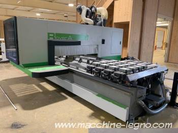
CNC ROVER A machining center
BIESSE's Rover A series machining centers are specially designed for daily milling and drilling operations on panels, doors, component doors and furniture.
The mobile gantry structure is made of extra-thick electro-welded sheet steel and stiffening hangers to minimize distortion during machining.
For movement of the moving column along the longitudinal axis (X axis) and in the transverse direction (Y axis), BIESSE has opted for a rack-and-pinion solution, enabling higher acceleration and speed parameters than those achievable with a ballscrew.
Controlled axis motors :
Brushless motors, controlled by digital actuators.
Hardened steel controlled axis guides.
Automatic centralized lubrication system.
Machine equipped with two vacuum pumps, 250 m3/h and 300 m3/h.
Activation of vacuum and pneumatic systems is available from any point along the machine's X work zone.
Working range (vertical electrospindle axis):
X= 5540 mm
Y= 1560 mm for 4 axes, 1570 for 5 axes
Z= 230 mm with modules H=74 mm /Configuration 1B and 3B
Z = 275 mm with modules H=29 mm / Configuration 1B and 3B
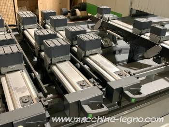
8 ATS aluminum worktops
1 X-axis metric ruler for correct positioning of worktops
8 metric rulers on Y axis for correct positioning of workpiece clamping systems
32 carriages 132 x 132 x H 41.5 mm
Each carriage rotates the modules every 15°
32 plugs for closing the carriages
Additional quick-fit connections for special jigs
EPS (Electronic Positioning System) automatic positioning for worktops up to 1550 mm, allowing automatic positioning of clamping devices at selected points.
An entire half machining zone can be positioned in hidden time while the machine is machining (avoiding major productivity losses).
Each carriage is equipped with a blowing system to ensure that the machining plane on which it slides is always clean.
2 X-shaped machining zones
Reference systems :
Rear line stop with 115 mm travel
Intermediate line stop positioned at 685 mm
Front line stop positioned at 1348 mm
4 side stops with 140 mm travel (2 left and 2 right)
2 additional side stops (1 left and 1 right)
1 retractable linear stop for raw panels.
Vacuum module 132 x 146
Vacuum module 132 x 75
Vacuum module 132 × 54
CFT system :
Vacuum system for aluminum CFT modules, for left work area
Aluminum vacuum module, dimensions : X=1250 mm, Y=625 mm, H=74 mm, for modular worktops
With this solution, it is possible to prepare a continuous surface for thin/flexible panels or for nesting, bending, etc
Uniclamp vice
Support base 130 x 130 mm
Flat disc 130 x 130 mm
Double-movement Uniclamp vice
Circular support base, diameter 130 mm
Clamping workpieces thicknesses from 40 to 98 mm
Horizontal vice, height 74 mm
Chip and waste conveyor belt
Configuration (3B) :
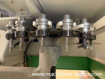
Machining unit
5 axis 13kW electrospindle, up to 20000 RPM
HSK F63 spindle
Liquid-cooled
C axis sewing : 360° continuous rotation
Maximum undercut angle: -5°.
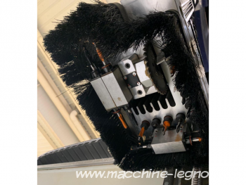
Drilling unit
BH 17 L drilling head
Up to 17 independent tools
Single and multiple drilling
Work on all 5 faces of the workpiece and grooves with X-direction blade on the upper face.
10 independent vertical spindles, 32 mm centres
5 in X direction
5 in Y direction
3 opposite independent horizontal spindles, 32 mm pitch
2 in X direction
1 in Y direction
1 circular blade ⌀ 120 mm
For groove in X direction (useful cut 25 mm)
Multifunctional unit
1 circular blade ⌀ 300 mm
2 independent Z axes (1 for the electro-spindle and 1 for the drilling and multi-functional groups)
Reinforced revolver-type tool magazine
Mounted on X carriage
Maximum 16 tools
113 mm tool spacing
Control and software :
BH660 digital control system entirely PC-based (Intel i5, 16GB RAM, dedicated graphics card and network card for desktop connection)
BIESSE WRT (Windows Real Time) : Simplified system structure further enhances reliability and performance.
Statistics are used to store machine and production events for the purpose of monitoring reliability and productivity.
Industry 4.0 - Integration with factory systems
Allowing the machine to be connected to the plant's IT systems, but also to be integrated into the plant's logistics system in an automated way.
bSolid software: for the design, simulation and management of machining processes on the center
bSolid features CAD design and project, CAD/CAM design and project, 3D graphic simulation, processing time calculation, work list design, etc.
SOPHIA-compatible machine : detects, checks, reports and solves any problems encountered during machine operation.
Electrical cabinet with air conditioner
Profile return function
Enables resumption of interrupted shaping following an emergency stop. The program restarts from the point at which it was interrupted (avoids throwing away the part that was being machined).


- France
- Second hand


